
The main reason catalyst metal impurities cause diamond graphitization is that they not only trigger destructive thermal stress inside the crystal but also directly act as "catalysts" to promote the heterogeneous nucleation of graphite.Specifically, catalyst metal impurities (such as Ni, Fe, Mn, etc.) lead to graphitization through the following two mechanisms:1.Promoting the heterogeneous nucleation of graphite (Core chemical/physical mechanism) During the growth of synthetic diamonds, bubble inclusions are extremely prone to form inside the crystal, and catalyst metal impurities like Ni, Fe, and Mn are usually attached around these bubbles. The presence of these catalyst metal impurities makes graphite highly susceptible to heterogeneous nucleation. Whether during the cooling stage in the later period of synthesis or in the subsequent high-temperature heating process, as long as specific temperature conditions are met, these impurities will cause the diamond matrix around the inclusions to begin transforming into graphite first.2.Huge internal stress caused by mismatched physical properties (Mechanical mechanism) After impurities such as catalyst metals enter the diamond crystal, due to the difference in atomic radius from carbon atoms, most of them exist in an interstitial state, meaning they are incoherent with the diamond matrix. More importantly, the thermal expansion coefficients of the catalyst metal inclusions and the diamond matrix are different.When heating the diamond, due to their inconsistent expansion, the inclusions will exert an increasing internal pressure and shear stress on the surrounding diamond matrix.As the temperature rises, the yield stress of the diamond matrix will decrease. When the pressure generated by the internal inclusions equals or exceeds the yield limit of the diamond matrix at high temperatures, the diamond will undergo plastic deformation.Once plastic deformation occurs, the diamond matrix around the inclusions will begin to graphitize. At this point, plastic deformation and graphitization coexist, eventually causing the entire diamond crystal to be destroyed.
read more+
Specifically, distinction can be approached from the following core aspects:1.Detecting Absorption Wavelengths via Spectrometer Diamonds exhibit different colors because their internal "color centers" selectively absorb specific wavelengths of light. Observing the spectral absorption from ultraviolet (360nm) to infrared (800nm) is the foundation for distinction. Natural diamonds (most commonly Type Ia) typically feature naturally formed, concentrated N2 and N3 centers, which create strong light absorption bands at 478nm and 415nm, respectively.2.Identifying "Artificial-Only" Color Centers Analyzing the types of internal color centers can determine if a diamond has undergone artificial coloration:Natural Characteristics: Natural diamonds generally only possess N-series color centers (N1—N9) intrinsically.Artificial Characteristics: Artificial processes like radiation irradiation and heat treatment forcefully impact the crystal or induce atomic movement, creating crystal defects not found in nature.3. "Hard Evidence" of Specific Colors (e.g., Purplish-Red) The materials highlight a specific color center that serves as direct proof for differentiation:N—V Color Center: This structure absorbs wavelengths between 490—640nm, giving the diamond a purplish-red hue.The literature explicitly notes that this N—V color center can only be produced in synthetic (artificial) diamonds.Therefore, any purplish-red diamond containing this specific color center can be definitively identified as an artificial product.If the spectrum detects color centers from the H series (H1—H18), GR series (GR1—GR8), R series (R9—R11), or TR series (TR12—TR17), it proves the diamond has undergone an artificial manufacturing process.4. Considering Color Rarity Artificial coloration is often utilized to produce "precious" hues rarely found in nature. For instance, specific "precious" yellow tones created via 600~800℃ heat treatment (associated with N3 color centers), as well as purplish-red colors, are exceptionally rare in natural diamonds.When encountering fancy color diamonds with such flawless and rare hues, it should arouse high suspicion, necessitating spectroscopic testing to verify whether their color center structures were artificially induced.
read more+
As an important sealing and pressure-transmitting medium in the synthetic diamond system, the internal chemical composition and impurity mineral composition of pyrophyllite will directly affect the pressure transmission, sealing, and high-temperature/high-pressure stability of the medium, thereby significantly affecting the synthesis quality and yield of diamond. The specific impacts are mainly reflected in the following aspects:1. Impact of chemical compositionSilicon dioxide (SiO₂): Pyrophyllite with a higher SiO₂ content usually has better pressure transmission, but if the content is too high, it will cause the raw material to become hard, thereby reducing its sealing performance.Aluminum oxide (Al₂O₃): Pyrophyllite with a higher Al₂O₃ content often exhibits better sealing properties.Iron oxide (Fe₂O₃): Pyrophyllite with a higher iron content has a higher internal friction coefficient.Moisture (structural water/loss on ignition): Pyrophyllite with a higher loss on ignition has a softer texture and good resilience, but an excessively high water content is harmful to diamond synthesis. Under high-temperature and high-pressure environments, free moisture and crystal water will promote the phase transition of pyrophyllite (generating coesite and kyanite) and form a harmful hard crust layer, which will hinder the effective transmission of pressure and interfere with diamond synthesis.2. Impact of impurity mineral compositionLayered and non-layered impurity minerals: Pyrophyllite ore is often accompanied by various impurity minerals. Among them, as long as the content of layered structure impurities (such as kaolinite, sericite, chlorite, etc.) does not exceed 10%, it will not affect the pressure transmission performance of pyrophyllite. However, the content of non-layered structure impurities must be strictly controlled within 5%, otherwise, it will destroy the static pressure rheology of the pressed pyrophyllite powder block, resulting in uneven pressure transmission.Impurity minerals containing iron, titanium, etc.: Although pure pyrophyllite has extremely high pressure transmission, its sealing performance is poor. Experiments show that the presence of small amounts of impurity minerals such as hematite, ilmenite, limonite, and rutile in pyrophyllite can actually effectively improve the sealing performance of the medium.Quartz: An appropriate amount of quartz is beneficial to the synthesis. Studies have pointed out that when pyrophyllite contains about 20% quartz as a pressure-transmitting medium, it not only helps to reduce the synthesis pressure, but also significantly improves the quality of diamond products.In summary, to ensure the high quality of synthetic diamonds, the selected pyrophyllite not only needs to have moderate hardness (to balance pressure transmission and sealing) but also needs to have its specific impurity minerals and moisture controlled within an optimal ratio range. For instance, the loss on ignition should be controlled at 5.5%~7.5%, aluminum oxide at 27%~35%, and silicon dioxide at 47%~65%. Excessively high purity or excessive specific impurities will destroy the cavity environment, thereby reducing the synthesis quality of the diamond.
read more+
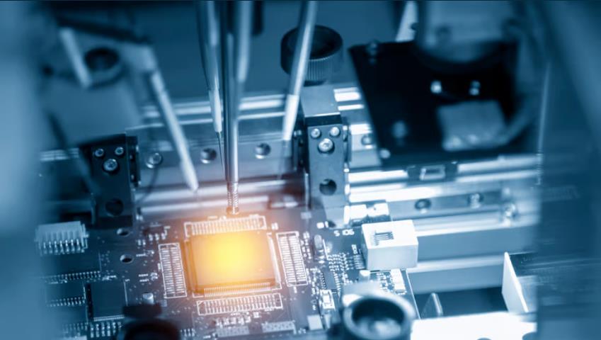
IIn the electronic components and microelectronics industry, the use of diamond films (CVD diamond) is primarily because it combines a variety of extreme and excellent physical, thermal, and electrical properties, which can solve the bottleneck problems faced by modern high-power, high-frequency, and high-density electronic devices. The specific reasons include the following core aspects:2.Extremely High Thermal Conductivity (The Ultimate Heat Dissipation Material)Modern electronic components (such as high-voltage power transistors, laser diodes, 5G/6G RF amplifiers, and CPUs) generate immense amounts of heat while pursuing miniaturization. Diamond is the material with the highest room-temperature thermal conductivity in nature, reaching up to 2000-2400 W/(m·K), which is several times that of copper. Using it as a heat sink substrate or heat spreader close to the chip's "hotspots" (such as adopting GaN-on-Diamond heterogeneous integration technology) can drastically reduce the device's junction temperature, thereby allowing the device to operate at higher power and ambient temperatures, and exponentially extending its service life.Perfect Combination of Thermal Conduction and Electrical Insulation Unlike highly thermally conductive metals such as copper or aluminum, diamond is simultaneously an excellent electrical insulator (its room-temperature resistivity can reach 1016 Ω⋅cm). This allows the diamond to directly contact electronic components for heat dissipation without the need for additional insulating layers that might impede heat conduction. It is highly suitable for packaging scenarios requiring strict electrical isolation.3.Excellent Wide-Bandgap Semiconductor Properties Diamond is hailed as the "ultimate material" for semiconductor technology. As an ultra-wide bandgap semiconductor, it possesses a bandgap width of 5.47 eV, and a critical breakdown electric field far exceeding that of silicon and silicon carbide (10-20 MV/cm, over 33 times that of silicon). Moreover, it has extremely high carrier mobility (at room temperature, electron mobility is about 4000 cm²/V·s, and hole mobility is about 3800 cm²/V·s). These properties enable diamond to be directly used in manufacturing next-generation ultra-high voltage, ultra-high frequency, and high-temperature tolerant semiconductor components (such as Schottky diodes and field-effect transistors).4.Extremely Low Dielectric Loss, Suitable for High-Frequency/Microwave Applications Diamond features a low dielectric constant and extremely low dielectric loss (tanδ<10−4 at 10 GHz). In microwave and high-speed digital circuits, as a substrate for passive RF resistors or high-power terminations, diamond can absorb immense thermal energy at frequencies up to 26.5 GHz or higher without causing RF signal distortion, exhibiting performance far superior to traditional Aluminum Nitride (AlN).5.Excellent Physical/Chemical Stability and Radiation Resistance Diamond possesses extremely high mechanical strength, chemical inertness, and corrosion resistance. It is chemically inert below 300°C, and remains absolutely stable at 600°C in the air or 1200°C in a vacuum, making it very suitable for high-reliability applications like aerospace. In addition, diamond's incredibly strong radiation hardness allows it to serve stably for long periods as tracking detectors in extreme high-energy particle collision or nuclear industry environments, such as at the European Organization for Nuclear Research (CERN).6.Excellent Thermal Expansion Matching Potential Pure diamond has a very low coefficient of thermal expansion (CTE) (approximately 0.8-1.0 × 10⁻⁶ K−1). In industrial applications, it is often combined with highly thermally conductive metals (like copper or silver) to create metal-diamond composites. These composites not only retain ultra-high thermal conductivity but can also have their CTE precisely tailored to match the levels of semiconductor chips like Silicon (Si), Silicon Carbide (SiC), or Gallium Nitride (GaN). This significantly reduces destructive shear stresses and micro-cracks generated by mismatched thermal expansion during rapid thermal cycling in the equipment.
read more+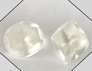
Although lab-grown diamonds have massive development potential in the current market, they still face severe challenges in terms of industrial chain structure, external competition, and their own brand building:1.Unbalanced industrial chain structure, with high-value-added profits flowing overseas Although China accounts for over 70% of the rough production in the global lab-grown diamond industry chain, this is mainly limited to the upstream manufacturing sector. The midstream cutting and polishing sector, which has extremely high added value, is a weak point in the domestic market. Reasons for this include a shortage of domestic professionals, high labor costs, and unequal domestic and export sales policies such as export tax rebates. Because India dominates this area, China's lab-grown diamond industry is basically in a state of "making wedding clothes for others," with the vast majority of profits flowing overseas.2.Facing marketing suppression from natural diamonds and the impact of value-preserving substitutes (like gold) In the terminal consumer market, lab-grown diamonds are encountering the dual impact of fierce external competition and changing consumer trends:Marketing counterattacks from natural diamonds: To maintain their status, the natural diamond industry often uses advertising rhetoric in marketing campaigns to publicly disparage lab-grown diamonds, describing them as a "boring" choice. While controversial, this rhetoric has indeed negatively affected consumers.Diversion to value-preserving products like gold: In the current environment, diamonds have poor liquidity, and consumers are paying more attention to gold jewelry with high practical value. Therefore, in addition to dealing with the counterattacks from the natural diamond industry, lab-grown diamonds must also face the trend of consumers shifting toward value-preserving products like gold.3. Lagging brand and channel construction, bogged down in low prices and homogeneous competition Currently, most lab-grown diamond companies have obvious shortcomings in commercial operations,:Lack of brand premium and experience: Currently, most lab-grown diamond companies are still stuck at the level of product production and low-price competition, lacking brand-building awareness and capability. This leads to severe product homogenization, a lack of brand premium, and makes it difficult for most consumers to experience a comfortable retail scenario.Polarized and chaotic online channels: On the one hand, online sales channels are flooded with cheap fakes, disrupting the market; on the other hand, although some traditional brands have opened online flagship stores, their overall marketing strategies are one-dimensional,.
read more+
Automated synthetic diamond cutting comprehensively reduces production costs primarily by introducing precision equipment, improving processing efficiency, reducing reliance on manual labor, and minimizing material loss. This is specifically reflected in the following key aspects:1.Lower the technical threshold and reduce reliance on highly paid skilled workers. Traditional diamond cutting relies heavily on the experience of technical workers and master craftsmen. Human factors have a large impact, so industry thresholds and labor costs are extremely high. Modern automated processes significantly increase mechanical involvement. By introducing precision instruments to replace human judgment, it greatly reduces reliance on master experience and the overall technical threshold for cutting. Eliminating this dependence on manual labor not only directly saves expensive labor costs but also makes it easier for cutting mills to achieve miniaturization and industrialized operations.2. Optimize processing steps to comprehensively improve production efficiency and reduce material loss. Modern processes have achieved high levels of automation in the first three steps of diamond processing: design, division, and rounding, which inevitably leads to a significant reduction in production costs:Design stage: It abandons traditional design and marking that relied on manual experience. Instead, it uses precision instruments for three-dimensional scanning and modeling, utilizing algorithms to calculate the optimal cutting solution, thereby minimizing the negative impact of human factors.Division stage: Laser cutting technology is used to replace traditional sawing or cleaving. Traditional cleaving carries higher risks and sawing results in more loss. Laser cutting not only avoids risks and reduces rough stone loss but also greatly improves efficiency. For example, a rough stone of about 3 carats only takes 10 to 15 minutes to be automatically cut by a machine with very little manual intervention.Rounding stage: It discards the traditional slow and inefficient method of rotating and grinding two diamonds against each other. Instead, it uses an automatic grinding machine with a rough grinding wheel, further reducing manual intervention and greatly improving processing speed.Cutting and polishing stage: It innovatively introduces a brand new modern mechanical drilling jig (i.e., the "lapidary arm" or "cutting arm"). It not only realizes multi-purpose use for one arm but can also be precisely controlled by a computer to process 57 or 58 facets of a round brilliant cut with high precision.3. Processing fees experience a cliff-like drop. The most direct manifestation of high automation is the massive reduction in the processing fee per carat. According to calculations, the manual cutting fee in India is currently about 300 to 400 RMB/carat, while China's domestic manual cutting fee is as high as 400 to 600 RMB/carat. In contrast, using automated cutting has a huge cost advantage: in small-scale automated cutting mills in Shenzhen, the processing fee can be as low as 150 RMB/carat. If the automated cutting mills are further moved to inland China, the cutting fee can even drop to an astonishing 60 RMB/carat.In summary, by subverting traditional heavy physical and experience-based operations, and utilizing modern instruments and computer controls, automated cutting has achieved rapid efficiency improvements and reduced losses in all procedures, thereby giving the synthetic diamond industry a tremendous cost advantage.
read more+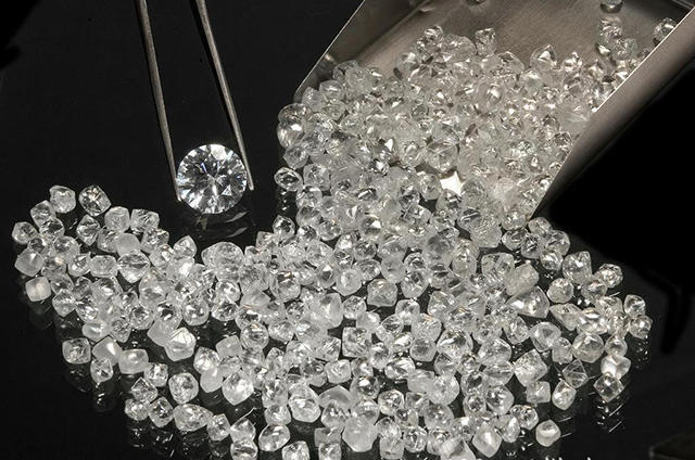
Graphite boronization can significantly improve the thermal stability of synthetic diamonds. Experimental data shows that after being held at 1000°C for half an hour, the compressive strength of ordinary 40/50 mesh diamonds decreases by about 40%, whereas boron-containing diamonds synthesized with boronized graphite only lose about 25% to 30% of their compressive strength. This lower strength loss rate indicates a marked improvement in thermal stability.The core principle behind this enhanced thermal stability lies in the improvement of the diamond's surface structure, which drastically boosts its oxidation resistance. The specific mechanisms are as follows:1.Diamond surface defects (dangling bonds): Inside the diamond, each carbon atom uses four valence electrons to form stable covalent bonds with four surrounding carbon atoms. However, carbon atoms on the diamond's surface only use three valence electrons to bond with internal carbon atoms, leaving an unutilized "dangling bond".2.Ordinary diamonds are easily oxidized: Oxygen atoms are electron-deficient; when oxygen comes into contact with the diamond surface, it easily attracts the extra electrons on the dangling bonds of surface carbon atoms to form bonds, ultimately resulting in the release of carbon dioxide (CO2) gas, which represents the oxidation process of diamonds at high temperatures.3.The stable protective role of boron atoms: Based on the excited-state electron distribution of boron, it is trivalent (i.e., has three valence electrons). During boronized synthesis, the three valence electrons of a boron atom can bond with the dangling bonds of the surface carbon atoms, forming stable covalent bonds.4.Stabilization of the surface structure: Once boron bonds with the carbon dangling bonds, the surface carbon atoms of the diamond no longer have extra, active valence electrons. This transforms the inherently unstable surface structure of the diamond into a stable one, effectively cutting off the reaction pathway between oxygen and carbon atoms.Therefore, it is precisely because boron atoms fill the electron vacancies of surface carbon atoms that boron-containing diamonds possess excellent oxidation resistance, reducing their loss of compressive strength in high-temperature environments and fundamentally enhancing the thermal stability of the diamond.
read more+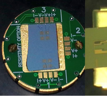
Core Advantages of Synthetic Diamond Heat Spreaders The core advantage of synthetic diamond as a heat spreading material lies in its extremely high thermal conductivity, making it an ideal functional material to solve the heat dissipation problems of high-power devices such as computer central processing units (CPUs) and light-emitting diodes (LEDs).Thermal conductivity surpassing traditional materials: It is often stated that the thermal conductivity of diamond is five times that of copper. Depending on the specific type, the thermal conductivity of Type I diamond is about twice that of copper, while Type II diamond is four to six times that of copper.Extreme thermal conductivity data: At a temperature of 273K, the thermal conductivity of Type IIa diamond can reach 2000–2200 W/(m·K), and that of isotopically pure diamond is as high as 3500 W/(m·K).Current Application Feasibility and Challenges Despite having tremendous theoretical advantages, the practical application of synthetic diamond as a heat spreading material currently faces some challenges, mainly reflected in two existing technological routes:1、CVD (Chemical Vapor Deposition) diamond films: This material has been partially trialed, but the cost is excessively high (about $10 per square centimeter, plus expensive processing fees). More importantly, its own thermal conductivity is not very ideal; measured results are similar to those of Type I diamond produced by the static pressure method, which limits its widespread application.2、Static pressure polycrystalline diamond sintered bodies: This route attempts to use low-cost static pressure single-crystal diamond (only a few cents per carat) as the raw material. However, the current process mainly produces Type Ib diamond, which has many internal structural defects and metallic inclusions, resulting in poor primary thermal conductivity. Furthermore, impurities and defects during the sintering process will further degrade thermal conductivity, and the final product's thermal performance may only be comparable to copper. It also faces the problem of high sintering and post-processing costs.Ideal Solutions and Future Feasibility As long as the correct technological route is adopted, it is entirely feasible to manufacture cost-effective heat spreading materials using synthetic diamonds. To achieve this goal, breakthroughs are needed in the following areas:Leveraging the advantages of artificial manufacturing: With synthetic diamonds, it is possible to artificially control the chemical environment of crystal growth (such as controlling the composition entering the crystal) as well as the temperature and pressure conditions to ensure the growth rate and quality of the diamond crystals.Overcoming high-quality Type IIa single-crystal raw materials: Type IIa diamond possesses excellent thermal conductivity, which is essentially due to its relatively complete crystal structure and low nitrogen content. Under current technological conditions, it is entirely possible to grow this kind of high-quality single-crystal diamond.Optimizing advanced sintering processes: Once the issue of high-quality single-crystal raw materials is solved, advanced sintering processes should be adopted to minimize defects that hinder heat propagation, such as grain boundary impurities, pores, and additives inside the polycrystalline sintered body.In summary, as long as there is an awareness of independent innovation and practical solutions are found for the three major problems of single-crystal raw material quality, thermal conductivity loss caused by the sintering process, and overall cost control, synthetic diamond heat spreading materials are not only technically feasible but also possess immense application potential.
read more+
The fundamental reason why non-magnetic diamonds have higher strength than magnetic ones lies in the destruction of crystal growth and structure by magnetic impurities (inclusions).Pure diamond crystals inherently lack magnetism. The reason synthetic diamonds exhibit magnetism is primarily because, during the high-temperature and high-pressure synthesis process, residual ferromagnetic and paramagnetic substances from the catalyst (such as Fe, Co, Ni) form inclusions within the crystal. These residual impurities directly affect the crystallization quality of the diamond, which is specifically manifested as follows:Non-magnetic diamonds have higher crystallization quality: Microscopic observation reveals that non-magnetic diamonds, which are free from the interference of magnetic impurities, exhibit full crystal growth, very smooth crystal faces, and a higher proportion of complete crystal shapes. At the same time, they contain very few internal black spots and inclusions, and have good transparency. This intact and dense physical structure allows them to withstand larger breaking loads.Magnetic diamonds have numerous structural defects: Diamonds with magnetic impurities often have incomplete crystal growth and more surface defects. In addition, the crystals contain more black spots and inclusions, resulting in poor transparency. These surface etching pits, cracks, and internal impurities easily become weak points for stress concentration when subjected to force, thereby seriously damaging the compressive strength of the diamond.In short, the increase in internal inclusions and surface crystal defects caused by magnetic impurities is the core reason why magnetic diamonds become brittle and weak. In contrast, non-magnetic diamonds, with their more perfect smooth crystal faces and higher internal purity, exhibit a measured strength that is about twice as high.
read more+
Even if diamonds have the exact same strength and particle size, differences in their thermal stability will still exist, which is primarily caused by the different content of impurities (inclusions) within the diamond crystals.Impurity content determines the initial weight-loss temperature: Experiments show that for multiple diamond single crystal samples with the same fracture load (strength) and particle size, their initial weight-loss temperatures vary significantly. This difference directly corresponds to the impurity content within the crystals: as the inclusion content within the crystal increases, the thermal stability of the diamond decreases accordingly.Impurity content is the decisive factor for thermal stability: Whether comparing diamonds of the same strength or of different particle sizes, test results indicate that the thermal stability of a diamond depends heavily on its own impurity content. High impurity content is the main reason for poor thermal stability.Internal stress destruction mechanism: As mentioned earlier, because the thermal expansion coefficients of inclusions (bubbles, catalyst metals, etc.) and the diamond matrix are different, shear stress is generated upon heating. The more impurities wrapped within the crystal, the greater the total shear stress generated when heated. This causes the diamond to reach its yield limit at lower temperatures, leading to plastic deformation and graphitization.Therefore, even if two diamonds exhibit the same macroscopic mechanical strength at room temperature, as long as there is a difference in the quantity of impurities trapped inside them, their tolerance in high-temperature environments (thermal stability) will be different.
read more+
Multiple activation treatment refers to processes such as double or triple multiple activation performed on the test core blank containing catalyst powder. First, thermal static degassing activation is conducted on the core blank within a specific temperature range and at a vacuum degree of 10−3 mmHg, ensuring that the powder core blank does not oxidize or sinter. After the degassing activation is completed, a second step of activation treatment is carried out under the protection of inert gas.Improving appearance and crystal shape: This treatment effectively removes oxygen and other impurities from the core blank to an extremely low level, making the synthesized diamond beautiful in color and highly complete in crystal shape (mainly hexahedrons and octahedrons).Increasing the proportion of coarse grains: It can significantly increase the percentage of coarse-grained diamonds. The result of the triple multiple activation treatment is particularly outstanding: the main peak of the particle size is concentrated at 45/50 mesh (accounting for 41.98%), and the secondary peak is at 40/45 mesh, with the sum of these two values exceeding 70%.Comprehensively enhancing mechanical properties: This process can significantly improve the static pressure strength and impact toughness of the diamond. It also improves the thermal impact toughness, resulting in a much smaller decrease in the toughness index of the diamond at high temperatures.
read more+
Manufacturing High-Efficiency Drilling Tools (Drill Bits): Boron-doped diamond is commonly used to manufacture drag bits and impregnated bits. For instance, in oilfield drilling, boron-doped black polycrystalline diamond bits can efficiently drill through hard rock formations like hard limestone and gravel, and the mechanical penetration rate can be more than twice that of ordinary polycrystalline diamond bits. When drilling into rocks like dolomite marble, the drilling efficiency is significantly improved, and the cost is greatly reduced.Producing Durable Cutting Tools (Circular Saw Blades): Leveraging its high wear resistance and excellent self-sharpening properties, boron-doped diamond is made into circular saw blades widely used for cutting high-hardness and brittle materials such as high-voltage electrical porcelain (containing corundum), optical glass, granite, and marble. Compared to ordinary diamond saw blades, its cutting efficiency is greatly enhanced, its service life is extended by several times, and processing costs are significantly reduced.As High-Performance Cutting Tools: Boron-doped polycrystalline cutting tools are highly effective in machining metal and non-metal materials (such as fiberglass and powder titanium alloys). Due to its surface chemical inertness, when cutting iron-group metals like high-hardness quenched steel, it not only prevents the workpiece from burning but also completely avoids "sticking" and the formation of built-up edges, thereby significantly improving the machining quality of the workpiece and the durability of the toolManufacturing High-Efficiency Grinding Tools (Abrasives): Boron-doped diamond abrasives are particularly suitable for grinding hard, tough, and difficult-to-machine materials. When grinding hard alloys, its efficiency is about 30% higher than that of ordinary diamond abrasives. For specific workpieces like fuel injector nozzles, its efficiency can even be several times that of ordinary diamond or CBN (cubic boron nitride) abrasives.Applications in the Electronics Industry (Semiconductor Materials): Because the introduction of boron atoms gives the crystal excellent hole-conducting characteristics, blue boron-doped diamond crystals are directly used as semiconductor materials in the electronics industry.
read more+The intersection of Jingjin Road and Wei Yi Road, Luoxin Park, Economic and Technological Development Zone, Xin'an County, Luoyang City, Henan Province, China
+86 0379-6068-6876 |